|
Operational and Installation Guidelines :
Please read these Operational and Installation Guidelines before installing the “DDP” Delivery/Demand Pump. If additional help is needed, please consult the Factory.
CAUTIONS:
- Water pipe connections and fixtures directly connected to a potable water supply shall be sized, installed and maintained in accordance with Federal, State, and local codes.
- Do not operate the pump above the pressure limitations specified on the data label.
- Never operate the pump in a harsh environment or hazardous atmosphere, since motor brush and switch may cause electrical arcing.
- Consult with the factory if the pump is to be used with fluids other than water. Do not use with flammable or hazardous fluids.
- As long as there is inlet water pressure, the pump will not stop forward flow of water even if the motor is turned off. Be sure the system has positive means of shutting off water supply.
- Always consider electrical shock hazard when working with and handling electrical equipment. If uncertain, consult an Electrician. Electrical wiring should only be done by a qualified Electrician per Local and State Electrical Codes.
MOUNTING:
- The pump should be mounted in a dry place and away from any source of heat. If an enclosure is used, special instructions for cooling the motor may be necessary. Consult the Factory.
- Do not subject the pump to extreme high or low (freezing) temperatures while in operation. (Operating ambient temperature range is 32ºF to 115ºF).
- The pump may be mounted horizontally with the outlet port on the right when viewed from the pump end or with the pump above the mount; or vertically with the pump above or below the motor.
PLUMBING:
- The pump is equipped with either a pressure sensing demand switch, a bypass relief valve, or both which controls the maximum safe operating pressure.
- We recommend use of flexible tubing with proper pressure rating.
- Pump will prime only if all pressure is relieved from outlet port.
- It is recommended that debris-free water be pumped or an in-line sediment filter (100 mesh) be installed at the inlet side to keep foreign debris out of the system.
- The pump should always be mounted prior to any components which could introduce particles to the water; thus, preventing them from entering the pump chambers and possibly causing clogging.
- Avoid any sharp bends which may crimp tubing and restrict flow. Use 90º elbow fittings if necessary. Aquatec provides pumps with different kinds of fittings. Please consult Factory for your needs.
ELECTRICAL:
- The DDP series pumps are designed for intermittent duty, but may run continuously if the motor temperature does not exceed the recommended limit. Some DDP Series Pumps are equipped with thermally protected motors and in case motor temperature exceeds thermal cut-out rating, pump will shut down and will not restart until motor cools down to specified temperature. Please consult the appropriate Data Sheet for continuous running parameters, noting the effect of rapid On/Off Cycling (see below).
- If a power supply is used with the system and the supply is not furnished by Aquatec, it will need to be reviewed for correct application and approval by Aquatec.
INSTALLATION PROCEDURE :
The basic demand pump is controlled by a built-in pressure sensing demand switch. When a faucet or valve is opened down stream of the pump, line pressure drops, thus starting the pump automatically. Conversely, when the valve shuts, the line pressure increases turning the pump off automatically. The pressure switch actuates in response to the pump outlet pressure at a predetermined and preset pressure. The pump label indicates the pre-set OFF pressures. Typically, the OFF pressure is accurately set at the FACTORY and the ON pressure is within an allowable range below that value. In response to the characteristics of the system in which the pump is installed, such as the flexibility and length of the tubing, and the faucet or valves and the duration that they are open, these pressure settings may vary. Therefore, changes in pressure settings is expected with use and over time. If the pump does not have an integral pressure sensing demand switch (i.e. pump is operated with an external control), pump will be equipped with a bypass relief valve (bypass is factory preset). Read the OPERATIONAL AND INSTALLATION GUIDELINES above carefully before starting to install the pump. Consult the Factory if there is any question. Determine the optimum location for your pump before proceeding.
- Turn off the water.
- Cut the flexible tubing in sufficient length to avoid any stress on the tubing where it connects to the pump or the fitting on any accessory.
- Insert tubing into pump ports. If fittings are John Guest type, be sure tubing is inserted past the resistance point until it bottoms out against the port stop. If compression fittings with threaded nuts are used, insert tubing until it bottoms out in the port and hand tighten the compression nut until the connection is tight. Then use a wrench to tighten the nut 1/2 turn clockwise or follow the wrench tightening instructions provided by the fitting manufacturer.
- The “DDP” pump is now ready for operation. Open the inlet water valve if any to allow water to flow to the pump.
- If the power source is a transformer, plug the appropriate Aquatec supplied or approved transformer into the receptacle and connect the pump to the transformer. If the power source is not a transformer, connect the pump to the appropriate power source. Open the discharge or dispensing valve. Allow water to circulate, purging any entrapped air.
- The pump will now start building pressure. Operating pressure will vary with flow rate, flow valve, feed-water pressure and line voltage. Check for fitting leaks.
- If compression fittings with threaded nuts are used, observe any leaks after pump has run for approximately 15 minutes. Further tighten compression nuts approximately 1/8 to 1/4 of a turn on all fittings in the system. Wait 15 minutes and repeat the leak check. NOTE: Further adjustments should not be necessary although it may take several days of operation before all the air has been purged and the system is stabilized.
- ADJUSTING THE PRESSURE SWITCH. Should the pressure switch OFF setting vary with use and time to an unsuitable value, it may be adjusted for optimum performance. Turn the set screw clockwise to increase the OFF pressure setting and counter-clockwise to decrease. The screw should not be adjusted more than one turn without consulting the Factory. Excessive adjustment of the pressure switch could cause low system pressure, and rapid ON/OFF cycling, reducing pump and motor life. Damage may also occur if recommended maximum pressures are exceeded. The Warranty does not cover improper adjustment of the pressure switch.
- Rapid On/Off Cycling must be limited to no more than 6 times per minute, even if the pump is operating in the Continuous Duty zone. Cycling could cause the motor to heat beyond the recommended maximum temperature, and reduce the operational life of the pump and pressure-sensing switch.
SERVICING:
- Every Year: Check system against operating standards. If continuous duty, replace lower housing assembly
- Every Other Year: Check against operating standards. If continuous duty, replace motor
- Every Fifth Year: Replace valves
|
 RODI SYSTEMS
 DI RESIN - DEIONIZATION
 RO SYSTEMS
 FILTERS
 MEMBRANES
 WATER TESTING
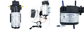 RO/RODI PUMPS
 PARTS & FITTINGS
 FAQ
FAQ


